

Background
Context
Now that I have developed a rough prototype of the shotgun device (V1) in Arduino (add link when available), I want to design custom hardware and firmware for the shotgun device (V2), full description here. This includes writing "proper" embedded C, something which writing Arduino code mostly abstracts away. I am using the Nordic Semiconductor nRF52 chip series, which has a nifty little example board called the Thingy52. I will be writing firmware on the Thingy as a proof of concept since my final design will essentially be a Thingy with fewer sensors on-board, utilising the same SDK.
Purpose
One of the core components of the firmware is interacting with the on-board sensors, and to do this I need to use a driver. I have looked through the SDK drivers, and although complete, are quite difficult to wrap your head around if you haven't been doing writing embedded firmware for years. As a stepping stone, I decided to write my own simple driver for a 3-axis accelerometer which communicates over I2C with the nrf52 microcontroller.
Scope
I want to make a driver that:
- Initializes the two-wire interface (TWI) or I2C
- Initializes the sensor to the desired configuration
- Poll sensor data in the x-axis When I achieve this, I can start writing a driver for the MPU9250, which also has a gyroscope so I can implement a complimentary filter for attitude estimation
Using the LIS2DH12
It All Starts with the Datasheet
Looking up the LIS2DH12 datasheet , we can see on the first page its main features. We can tell this is probably a sensor designed for mobile phones, or similar devices since it has orientation detection, sleep-to-wake and return-to-sleep, among some other neat integrated features. Although these are cool features, we are only interested in reading accelerometer data. The main features we will want to configure will likely be:
- Accelerometer full scale (FS)
- (First in First Out) FIFO output register mode
- Output Data Rate (ODR)
Communication with the Microcontroller over I2C
The sensor can use either SPI or I2C, but it is already wired as I2C on the Thingy52, so I don't have to choose! For I2C we need to know the IC's I2C address, or Slave Address (SAD), which is configurable as shown on p.25 of the datasheet:
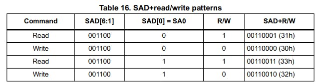
The SAD is 7-bits long, but the least significant bit is configurable to allow for 2 possible addresses (in case some other sensor happens to have the same address). When the master (microcontroller) sends a message to a slave (8-bit), it will send the SAD followed by a read or write bit depending on if it want to write or read data from the slave.
Important Registers
To communicate with the sensor over I2C, we now just need to know which registers we want to read/write to, and how the data should be formatted. For the most part, the default settings are OK for the simple driver here, so I will only mention the that are of interest.
Setting ODR
ODR is set by the CTRL_REG1, whose bits are shown below. The ODR bit values allow us to set the desired output data rate. The bit values for various output data rates an power modes are also shown below.

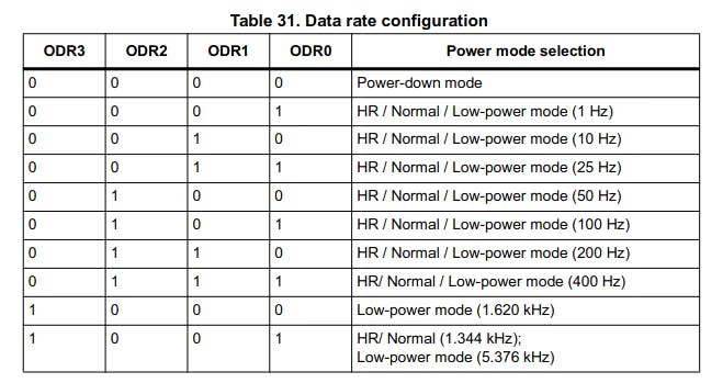
We want to operate in normal mode with an ODR of 400Hz, so we use 0111 for our ODR bit values. LPen bit enables the low power mode so we set it to 0. The remaining bits are to enable the 3 axes which we do by setting them all to 1.
Setting FS and Normal Mode
These are set in CTRL_REG4, whose bits are shown below.

For a FS of +/-16g, we set FS1 and FS0 to 1 (FS table is p.10). Also we want to be in normal mode so the HR bit is set to 0. All other bits are kept to their defaults.
Reading Accelerometer Data
The accelerometer data can be read by the registers OUT_X_L (lower 8 bits) and OUT_X_H (higher 8 bits) (also 2 for each other axis). The datasheet says it is formatted as left justified 2's compliment. This means that the data is shifted to the left and padded with zeros in the lower bits that aren't used by the output variables. Since we are in normal mode which used 10-bits of data per sample, the 6 lowest bits in the OU_X_L register are not used. This means that to get the x axis acceleration value we need to:
- Read lower 8 bits
- Read higher 8 bits
- Combine lower and higher bits into a signed 16-bit int
- Shift right by 6
- Multiply by the resolution (determined by the FS)
ADD DIAGRAM
Here the resolution is 48 mg/bit since we are using 10-bits to represent the data with a FS of +/-16g (datasheet p.10). You can see how I implemented this when I show my code.
Implementation
The implementation of the driver has the following steps:
- Setup a I2C connection
- Initialize the sensor
- Read the sensor values Luckily for us, the Nordic SDK has the low level I2C driver already written, so we just need to initialize the I2C driver from the SDK. The rest we will implement!
Defining Sensor and I2C Parameters
As good coding practice we should have all "magic numbers" as defines so they are more readable. In my case, the I2C parameters are defined in my board definition header file pca20020.h, and the sensor registers and parameter values are in the drv_acc_lis3dh_types.h so I include them both. Luckily for me, these were already written but you could easily write your own by using the datasheet as a reference. The important defines to have here are the device address and the register addresses that we want to read/write to which are, in this case:
#define TWI_SCL_EXT      15
#define TWI_SDA_EXT      14
#define LIS2DH12_ADDR    0x19
#define CTRL_REG1        0x20
#define CTRL_REG4        0x23
#define OUT_X_L          0x28
#define OUT_X_H          0x29
Because the pad SA0 is connected to high voltage on the board, the address is 0x19.
Initialize a I2C connection
We need to first create a TWI instance:
static const nrf_drv_twi_t m_twi = NRF_DRV_TWI_INSTANCE(TWI_SENSOR_INSTANCE);
With this we can create a TWI initialization function:
void twi_init(void)
{
    ret_code_t err_code;

    const nrf_drv_twi_config_t twi_lis2dh12_config = {
        .scl                = TWI_SCL_EXT,
        .sda                = TWI_SDA_EXT,
        .frequency          = NRF_TWI_FREQ_400K,
        .interrupt_priority = APP_IRQ_PRIORITY_HIGH,
        .clear_bus_init     = true
    };

    err_code = nrf_drv_twi_init(&m_twi, &twi_lis3dh_config, twi_handler, NULL);
    APP_ERROR_CHECK(err_code);

    nrf_drv_twi_enable(&m_twi);
}
In the twi_lis2dh12_config variable we define the clock pin (SCL) and data pin (SDA). From the documentation, the LISD2DH12 is connected to the TWI_SCL_EXT and TWI_SDA_EXT pins. We also set the com frequency. The interrupt priority here doesn't matter since our code is only doing one thing, but we just set it to high. The TWI connection is then initialized and enabled using our twi instance m_twi. One last thing we need for the TWI connection: a twi_handler function. This is called whenever a TWI transaction is complete (as far as I can tell). For now, I will just set a variable that will track when TWI transactions are complete:
static volatile bool m_xfer_done = false;
void twi_handler(nrf_drv_twi_evt_t const * p_event, void * p_context)
{
    m_xfer_done = true;
}
Anytime a TWI transaction is requested, the m_xfer_done is set to false and when the transaction is complete, set to true again. Like this we can tell if the TWI port is busy or not. If this were a proper driver, you would use this function to handle all possible cases using the info in the p_event variable.
Configure the Sensor
The configuration code is just setting the CTRL_REG1 and CTRL_REG4:
/**
 * @brief Function to configure LIS3DH
 */
void LIS3DH_cfg(void)
{
    /* Set CTRL_REG_1 for ODR of 400Hz */
    ret_code_t err_code;
    m_xfer_done = false;
    uint8_t conf = (BIT_6 | BIT_5 | BIT_4 | BIT_2 | BIT_1 | BIT_0);
    uint8_t reg[2] = {CTRL_REG1, conf};
    err_code = nrf_drv_twi_tx(&m_twi, LIS2DH12_ADDR, reg, sizeof(reg), false);
    APP_ERROR_CHECK(err_code);
    while (m_xfer_done == false);

    /* Set FS of +/- 16g in CTRL_REG_4 */
    m_xfer_done = false;
    reg[0] = CTRL_REG4;
    reg[1] = 0x30;
    err_code = nrf_drv_twi_tx(&m_twi, LIS2DH12_ADDR, reg, sizeof(reg), false);
    APP_ERROR_CHECK(err_code);
    while (m_xfer_done == false);
}
To request a transaction with a sensor over I2C with the Nordic SDK, we use the nrf_drv_twi_tx function. The function takes the twi instance, the device address, and the buffer along with its size. In the case of writing to a register, the buffer contains two bytes: the register address and the register data. However, if we were to want to read a register (e.g. read the x-axis accelerometer data), we would only transmit a 1 byte buffer with the address of the register we want to read (see next section on reading data from the sensor). So for both registers we:
- set the transfer done flag to false
- set the register address and register data in the buffer
- write to the register using the
nrf_drv_twi_txfunction - run the error checker and wait for the transmit to be done
Reading the Accelerometer Data
The final function we need is to poll the accelerometer data. Now in this case, we are explicitly requesting the data from the sensor. However, there are other ways of getting the data, for instance by accepting an interrupt from the sensor when new data is available. Here is the function:
/**
* @brief read the x axis data
*/
static void read_x_axis_accel_data()
{
/* Ask for transfer of x-axis data lower digits */
m_xfer_done = false;
uint8_t reg = OUT_X_L;
ret_code_t err_code = nrf_drv_twi_tx(&m_twi, LIS2DH12_ADDR, ®, 1, false);
APP_ERROR_CHECK(err_code);
while (m_xfer_done == false);
/* Read x-axis lower digits */
m_xfer_done = false;
err_code = nrf_drv_twi_rx(&m_twi, LIS2DH12_ADDR, &x_axis_data_l, sizeof(x_axis_data_l));
APP_ERROR_CHECK(err_code);
/* Ask for transfer of x-axis data higher digits */
m_xfer_done = false;
reg = OUT_X_H;
err_code = nrf_drv_twi_tx(&m_twi, LIS2DH12_ADDR, ®, 1, false);
APP_ERROR_CHECK(err_code);
while (m_xfer_done == false);
/* Read x-axis higher digits */
m_xfer_done = false;
err_code = nrf_drv_twi_rx(&m_twi, LIS2DH12_ADDR, &x_axis_data_h, sizeof(x_axis_data_h));
APP_ERROR_CHECK(err_code);
//transform data into float
int16_t x_axis_int = (x_axis_data_h << 8) | x_axis_data_l;
x_axis_int >>= 6; //shift to account for left justified 10-bit
x_axis_data = ((float)x_axis_int) *48; //put into m/s^2 with fs 16g
}
1. Read the lower and higher 8-bits
We need to get both the lower and higher 8-bits of the accelerometer data. The process is the same for both: request the register data using the nrf_drv_twi_tx function then read the register data with the nrf_drv_twi_rx function. When using the nrf_drv_twi_tx, we only send a buffer of length 1 byte so the function knows we are requesting data, not writing it.
2. Translate the lower and higher 8-bits into a float
As mentioned in the "reading accelerometer data section" in the intro, we need to combine the higher and lower bits, shift the right to account for the left justified nature of the data, and finally cast to a float with a coefficient based on the resolution of the data. This is done in 3 last lines of code:
    /* transform data into float */
    int16_t x_axis_int = (x_axis_data_h << 8) | x_axis_data_l;
    x_axis_int >>= 6;                           /* shift to account for left justified 10-bit */
    x_axis_data = ((float)x_axis_int) *48;      /* put into m/s^2 with fs 16g */
We combine the higher and Lowe bytes together by shifting the higher bits left by 8 and doing an OR operation on both unsigned ints. This number is then assigned to a signed 16-bit int to account for the 2s compliment nature of the data. We are also using normal mode which has 10-bits of data per reading, hence the data is then shifted by right by 6. Also, with a full scale of +/-16g and 10-bits, the resolution is 48mg/LSB so the data is then multiplied by 48 and cast to a float.
Main Function and Testing
The main function simply initialises the I2C connection, runs the configuration function and polls the sensor every 500ms. Since I am testing the code in debug mode, I don't need to poll more often than that anyways:
int main(void)
{
    twi_init();
    LIS3DH_cfg();

    while(true)
    {
        nrf_delay_ms(500);

        do
        {
            __WFE();
        }while (m_xfer_done == false);

        read_x_axis_accel_data();
    }
}
The __WFE() is just a "wait for event" function in the SDK which we use while the I2C bus is busy (not that that should happen with this code...).
Now for testing! I tilted the Thingy in a range of +/- 90 degrees to see if the x-axis acceleration would go from about 1g -1gm, which it does from the below figure:
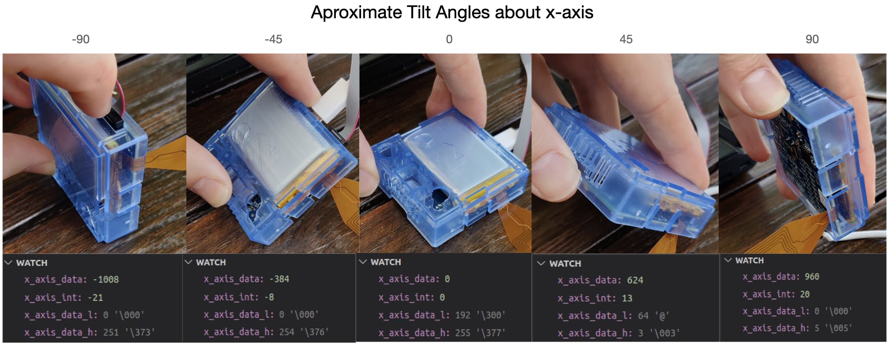
The x_axis_data variable contains the final data in float format, the x_axis_intcontains the data in 2s compliment (signed int) format and finally, the x_axis_data_l and x_axis_data_h contain the lower and higher 8-bits of the data taken directly from the accelerometer.
Discussion
Limitations
This driver is really a pretty terrible one. It is so specific that it has no reusability, does not allow more complex features, and probably has all sorts of bugs. But as a first attempt at programming a sensor over I2C, I would say it is a success.
Further Work
The next step is learning how to interface with the sensor I actually want to use: the MPU9250.