Introduction to the Propeller System Identification (PSI)
A load cell and instrumentation PCB for automated drone propeller system identification


Project Background
System Identification of Drone Propeller Systems
As part of my drone project, I would like to make an empirical model of the propeller systems on the drone. Having an accurate dynamic model of the drone will allow for a better overall drone system model, which will in turn improve the quality of the control system design. In addition, measuring things like variability between motors will allow some more advanced control system designs, which take into account plant variability. The goal of this project is to design a load cell and accompanying instrumentation to automatically perform drone propeller system identification.
Why Make instead of buy?
There are a few reasons why I want to make my own load cell and instrumentation instead of buying an existing solution :
- I worked on novel propeller system identification and load cell design during my Master's thesis. One of the challenges was ensuring dynamic load cell accuracy - I would therefore like to raffine this aspect of my work.
- I would like to extend my PCB design, instrumentation circuit design, and data acquision skills.
- I will have fuller control of the system and a better understanding of its capabilities and limitations
- I am also very interested in instrumentation in general, in particular automated system identification.
Subsystems and Project Roadmap
Here is a high-level block diagram of the PSI (propeller system identification) and associated systems.
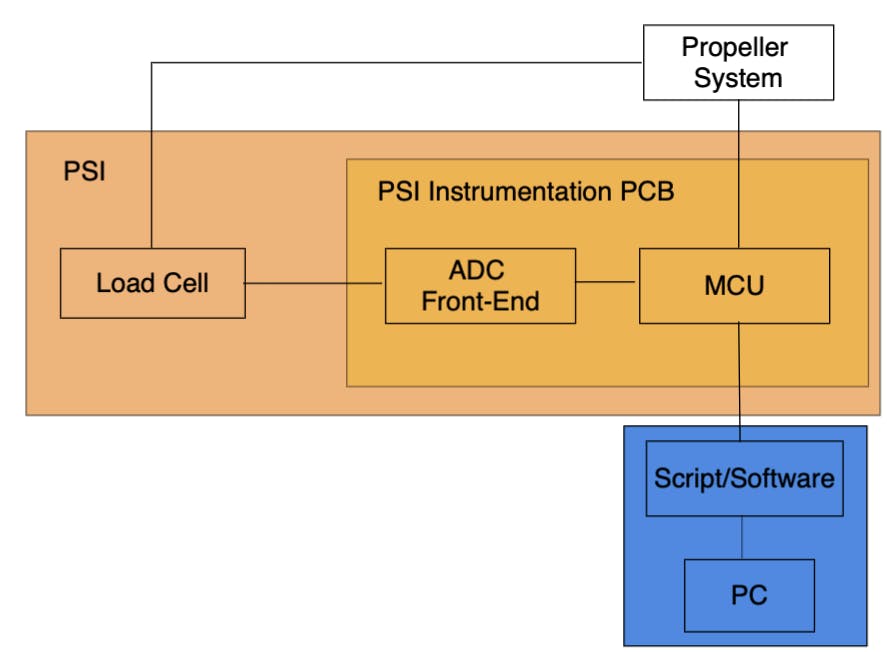
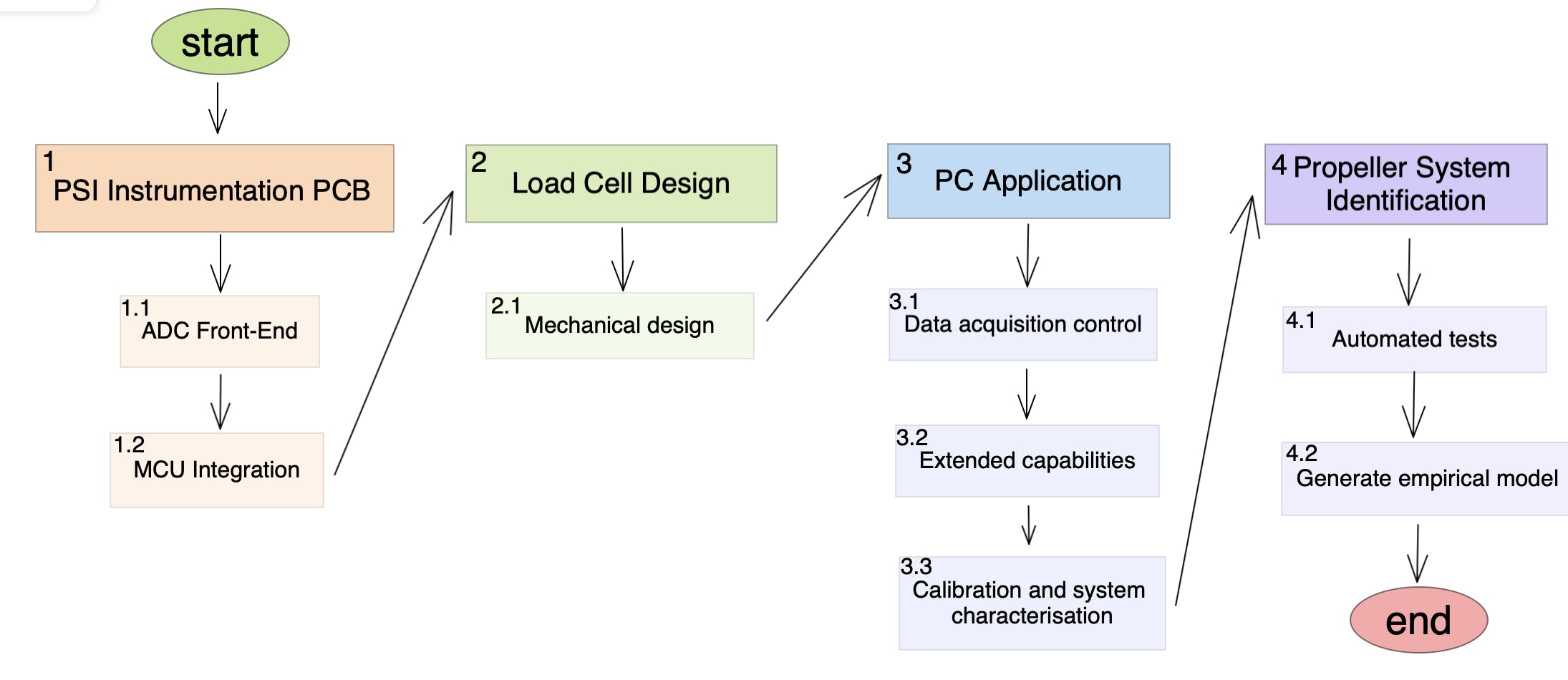
The PSI will include a load cell to measure the loads, and an accompanying PSI instrumentation PCB. The propeller system will be connected to the load cell (mechanically), and the electronic speed controller (ESC) PWM control signal will come from the PSI instrumentation. Finally, a PC with an accompanying application will control the instrumentation PCB, collect data, and analyse the results. The order of development will be as follows: